Meister BC-10L DRO
Getting Started
The best advise I can give
is lay the parts out and take your time in determining the best
locations for the
scales and display. Take into account where most of the chips fall and where any accessories bolt on such
as a follow rest. Also look closely to make sure drilling and tapping does not interfere with anything. Position
the display away from flying chips and take into account any glare from lighting.

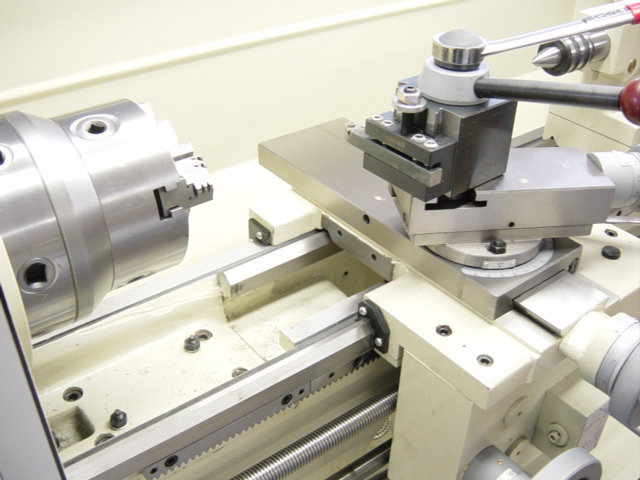
I started out by determining the placement of the "X" axis scale. The easiest place would have been on the front
of the compound slide shown above. I decided against this since it's directly under the cutting tool and this is
also where the follow rest attaches to the front of the saddle.
I chose to attach the X axis scale to the rear of
the compound slide shown above. One problem attaching
here is that the saddle does not have a flush mounting area shown with the red arrow. This is where the
reading head would attach to. I decided to remove the saddle and mill this area flush with the compound slide.
( Detailed information on installing the X axis scale can be found at the bottom of the page)
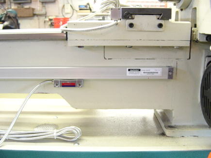
The Z axis scale was pretty straight forward and placed
below the removable gap shown
above.
( Detailed information on installing the Z axis scale can be found at
the bottom of the page)
I mounted the arm to a steel bracket that I bolted to the side of the electrical box.
The steel plate is 1/2" thick.
4 1/4" bolts attach the steel plate to the electrical box.
This works great and is very solid.
| Unpacking
the DRO |
Getting Started |
Mounting
"X" Axis Scale |
Mounting"Z" Axis Scale |
Comments |
Home |
Comments / Questions /
Contact Steve
This information is provided for personal use only.
Copyright 2002 / 2007
Steve Bedair